After completion of the restoration in the workshop at the Sheffield Hardware Hackers and Makers Hackspace, we needed to sort out the most important item in any workshop, the workbench…
The decision was made to build our own, not only would this work out cheaper for us but I can make it exactly how people want it. However there was a list of criteria that the workbench needed to have in order to fur fill it’s purpose in the Hackspace. Together we came up with a list of what we wanted the bench to feature:
– Provide a work surface that is suitable for people of all heights to work at.
– Allow the front part of the bench to overhang the frame so that things such as vices and clamps can be secured in place.
– Integrate storage shelf’s for boxes and tools both above and below the work surface.
– Utilise as much space as possible to increase storage area at the back section of the workshop.
– The work bench must be free standing as it is being constructed in a grade 2 listed building.
Method of joinery
Now I had a list of criteria to work to I could start to plan out what process I am going to use. My plan was to use through mortise and tenon joints. With this in mind I began to sketch out some ideas. Below on the left you can see the area that the bench would be constructed in. The workbench would be an ‘L’ shape, it would be 1900mm wide spanning the width of the rear wall, 1200mm from the back of the wall down the left hand side of the wall, the frame will be 600mm wide, the worktop height will be 1025 and the overall height will be 2000mm. You can also see the sketch that I made of the location where the support posts would be positioned.

Layout of the support posts

The area where the workbench will be built
By now I had a good understanding of what I needed to accomplish. In order to plan out how I was going to construct each individual component I started to draw out a 3D model of the workbench in FreeCAD.
Each of the individual components that made up the frame had to be designed individually. The construction consists of 8 vertical posts that support the through tenons witch are fixed in to. The 5 posts that surround the perimeter of the two walls are 2M tall, these will support the back half of the shelf’s that will rest above the work surface. The other 3 the posts surrounding the front perimeter will support the work surface from the bottom side of the work top and the shelf’s below.
CAD Work
Once all of the individual parts have been produced in FreeCAD they are exported as .step files so that they can be imported in to one model and assembled. The individual parts can then be moved around in different dimensions to make them all fit together. At the stage of assembling the parts it is clear if the design is going to fit together as intended, if say for instance a mortise has been placed to far down from the tenon to fit in to it at the correct level, this can be addresses by going back to the individual part and edit the mortise to the correct height.

Completed CAD model of the workbench
Cutting the timber and marking out the joints
Now that I have a design in place I can begin to cut the material to length. The supporting posts are 70×70 and the through tennons are 20×70 redwood PSE. All of the individual parts where cut to length. For the through tenon lengths that where all the same length I stacked 3 lengths of stock on top of each other and lined the ends up squer, not only did this save time but is also more accurate because they where all cut at the the same because one end of all of the material was square.
To mark out the positions of the mortises I used a tape measure, square and mortis marking gauge. I marked out the height of each mortis from the base and marked out a line on to the other relevant sides using a square. This process was repeated on all of the supporting posts. The image below shows part of a post that has been scribed out, 2/3 of the material will be removed from each side that has been marked, this section marked out is section where two through tenons will be seated to form a shelf.

A marked up post ready for machining
Machining the joints
Once all of the joints had been marked out I set up for machining. To drill out the material I used a used a drill mounted vertically in a plywood jig witch was made by a friend. The jig was made in two parts, the first was the base witch held itself central to the post with two bits of ply fixd on either side of the base. The other part of the jig was joined to the base by a set of sliding rails, with makes it easy to manoeuvre. The last feature is the depth stop, this was incorporated by using a bolt and two nuts, it ensured that the spade bit did not travel more than 45mm in to the timber.
There are three different types of posts in the workbench, the first have two mortises that meet at 90° the second has three mortises that meet as a ‘T’ and the last has a mortise on every side that meet as an ‘+’. The 90 posts sit in the far corners, ‘T’ posts sit in-between the posts in the far corners and the ‘+’ post sits directly in the middle of the frame supporting the central weight.
Once the bulk of the material has been drilled out of the mortises they are ready to be squared off. I started by cutting around the perimeter of the mortise, I did this by setting my chisel on the line and tapping it gently with a mallet to set in in place to stop it from slipping, I could than continue with a stronger strike to remove more material. Once I had been around the exterior of the mortise three to four times I could begin to start and lift material out. With the bulck of the waste removed I used a wider 25mm chisel to pair back additional material from the sides until the tenon fitted snugly.
Dry fitting
Now all the posts and through tennons have been mortised and squared off The individual sections that make up the workbench where offer up to each other before glueing. Offering up all the separate sections as shown below ensures everything will fit together as intended once it has been glued up this gives me the opportunity to pair off any excess material in the mortises using a chisel.

Offering up the components to each other
The assembly process
The workbench was assembled in three main sections, the back, the left hand side and the middle. I used an expanding glue witch was moisture activated, because this glue expands it fills gaps at the same time. The image below shows the back and left hand side being glued up. Once all of the back rails has been slid in to place along the back and side glue was applied in to the mortises, the tenon was then inserted in to the groove and a screw was driven in to hold the components in whilst the glue set.

Assembling the section of the workbench
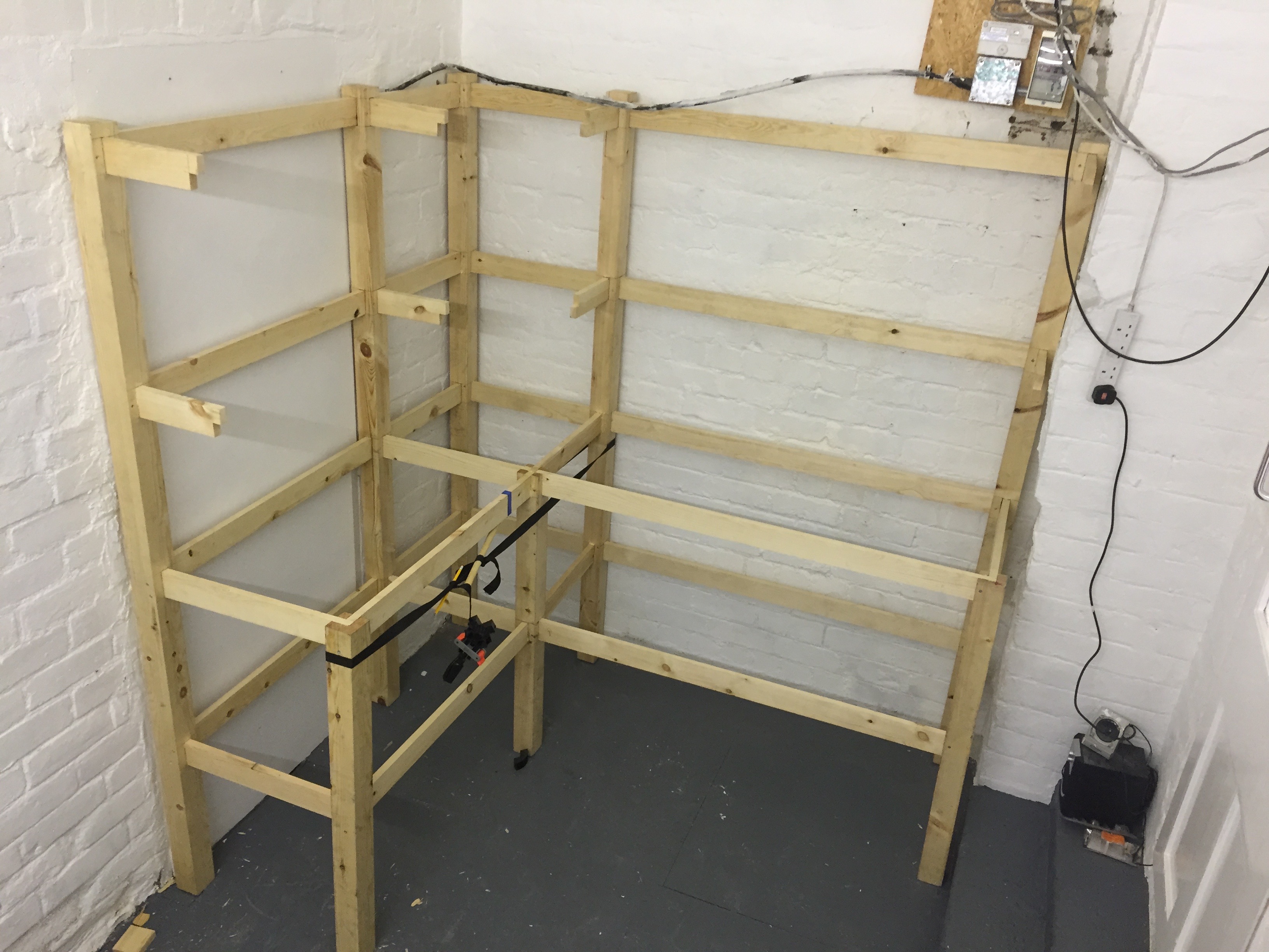
The assembled frame
Installing the shelfs and worktop
Once the frame had been completed the shelfs and worktop where installed. The shelves are 18mm OSB cut to size, the worktop is a piece of 25mm thick teak. To install the shelfs a measurement was taken of the length and width of the opening. Once this had been cut to size it needed to be shaped around the posts. The square cut outs for the posts where marked on and cut out. The shelf could then be fitted in place.
The worktop was mounted in two sections, the first was the pice that runs the length of the left hand side, towards the front side of the workbench a notch was cut out at 45 to allow the other pice to be seated on the rail with a corresponding notch in the other section of the worktop. With the worktop set in place the shelf support posts for the upper shelf’s where glued and inserted in to the cross tenons followed by a piece of OSB for the shelf.

almost completed workbench with upper shelf’s assembled
Overall this has been a great build and has produced some excellent results. The workbench fulfils it’s intended purpose, because of the method of joinery used it is a solid structure that will and will take many years of use. The worktop is at a suitable working height, an improvement witch I feel could be made is to install a backstop to prevent things from falling behind the worktop and add at least 4 double plug sockets along the back secured in angled back boxes, this in turn provides better power access for power tools and battery charges etc. The lower shelf’s make plenty of storage space for pats and components, as for the upper smaller shelf’s make an ideal place to put component trays and store power tools, it gives quicker access to the kit that will be used most often. I have enjoyed doing this build and have learnt some new skills along the way, I’m looking forward to future projects identical to this.
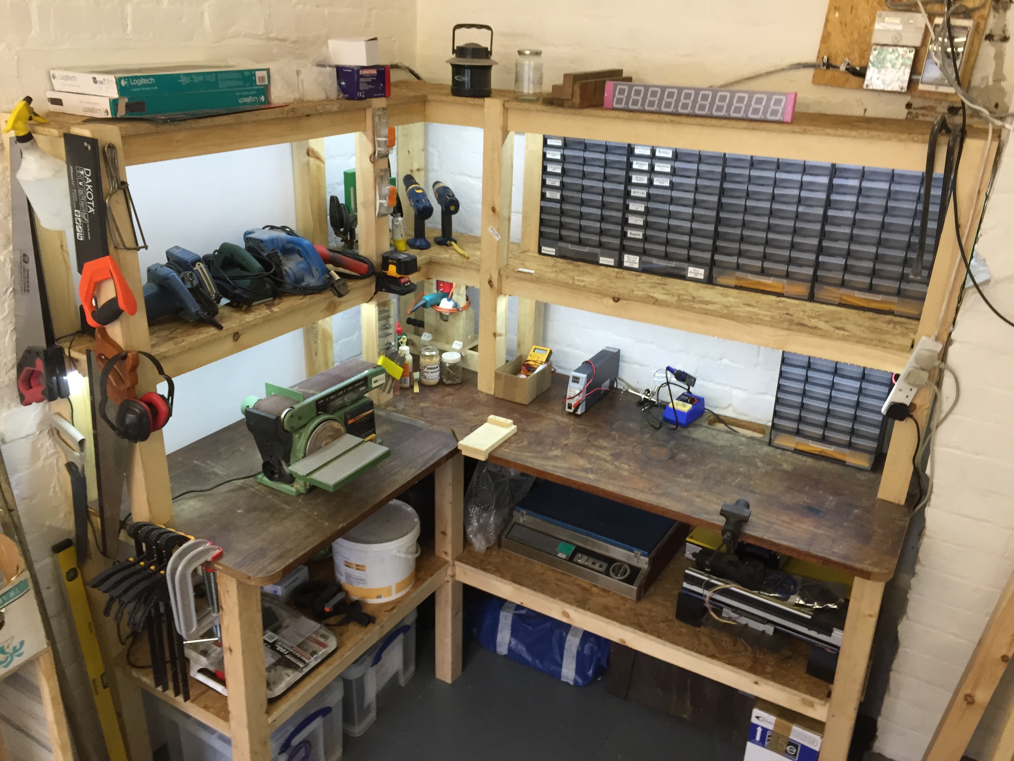
Compleated workbench
For more build images visit my Flicker page
